

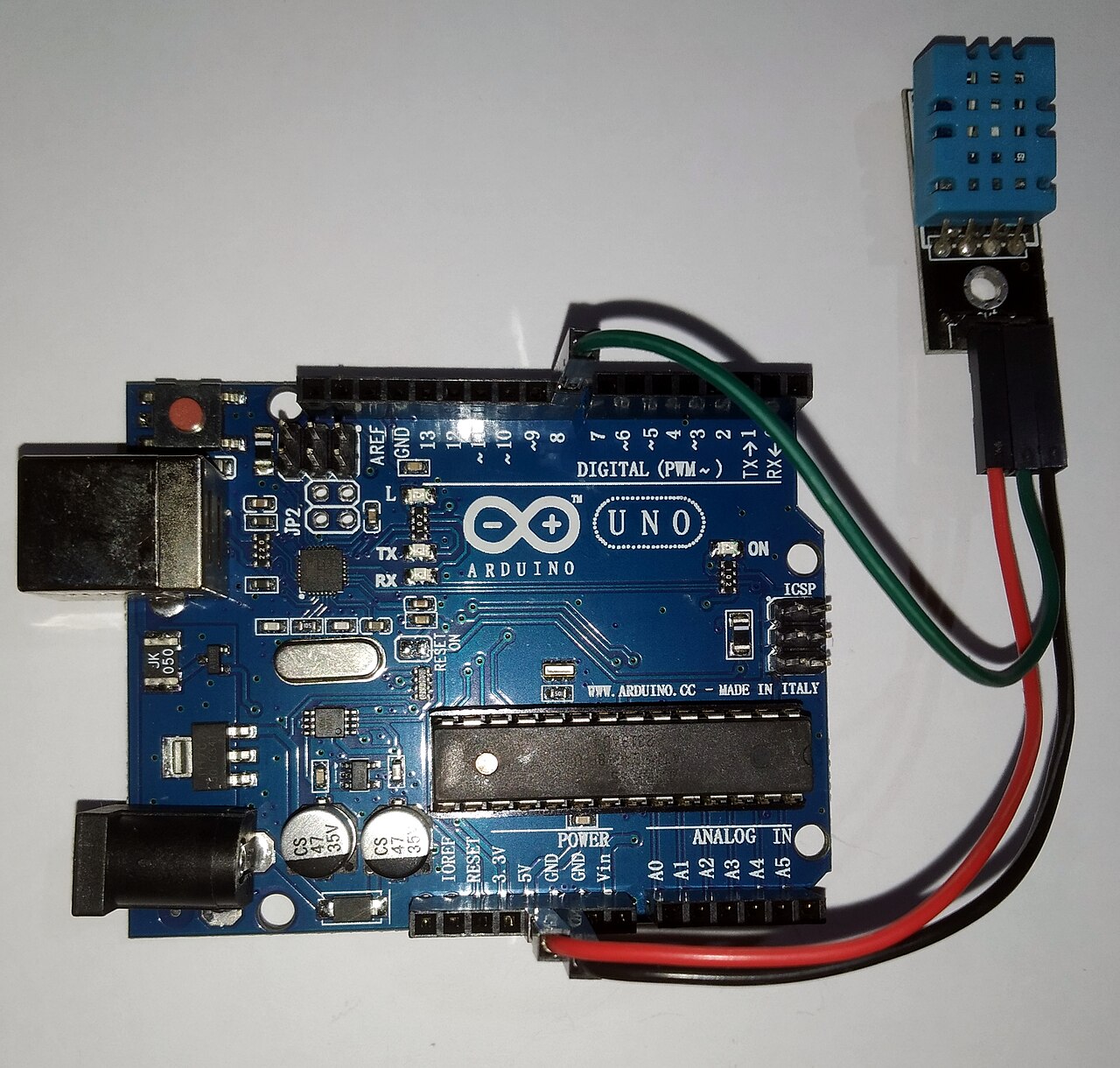
The solderless breadboard distributes 5 V and ground from the Arduino to the LCD, DHT22 pull-ups, contrast pot, and Ethernet shield support components. Clean power rails reduce mysterious LCD garbage and sensor timeouts.
Rail layout
- Red rail: 5 V from Arduino 5V pin (USB or barrel power when installed).
- Blue rail: Common ground tied to Arduino GND.
- Jumpers: Short, same-length wires where possible; one ground star point at the board.
LCD and sensor power
The 16×2 LCD draws modest current; DHT22 peaks during conversion. If cables run long to remote probes, consider a dedicated 5 V supply with common ground rather than starving the Uno regulator. Contrast pot wiring shares ground: see LCD GPIO map.
Bench verification
Measure rail voltage under load before sealing an enclosure. Troubleshooting steps live in circuit wiring troubleshooting. Full overview: Arduino circuit wiring.